Logging rock is a more demanding task than logging soil. Rock materials exhibit a far greater range of mineralogy, texture, and structure than soils, and the parameters that govern the engineering behaviour of a rock mass are not always immediately apparent from visual inspection alone. BS 5930:2015 provides the framework for rock logging in the UK, setting out a systematic approach to describing the rock material itself and the discontinuities that divide it into a mass. Understanding this framework, and applying it consistently in the field, is a foundational skill for any geotechnical or engineering geology practitioner working in rock.
Rock logging is carried out on core recovered from rotary boreholes, on exposures in trial pits or shafts, or on natural and man-made rock faces. In each case, the logger must assess both the intact rock material — its type, strength, weathering state, and other characteristics — and the discontinuities that cut through it: their orientation, spacing, persistence, aperture, infill, and roughness. These two elements together define the rock mass, which is almost always weaker and more deformable than the intact rock material itself. A granite may have an unconfined compressive strength of 150 MPa, but if it is cut by closely spaced, clay-infilled joints, the effective strength of the mass in engineering terms may be a fraction of that value.
Rock Types
The first step in rock logging is identifying the rock type. This requires a working knowledge of geology, since rock type is determined by the mineralogy, texture, and origin of the material — all of which must be assessed from visual inspection, supplemented where necessary by simple field tests such as the acid test for carbonates, the streak test for mineral identification, or the scratch test for hardness. Rock types are divided into three broad genetic categories: igneous, sedimentary, and metamorphic. Each category encompasses a wide range of specific rock types with very different engineering properties.
Igneous rocks are formed from the cooling and solidification of molten magma. Intrusive igneous rocks, such as granite, diorite, and gabbro, cool slowly at depth and develop large crystals, producing coarse-grained rocks of generally high strength and durability. Extrusive igneous rocks, such as basalt, rhyolite, and andesite, cool rapidly at the surface and are typically fine-grained or even glassy. Volcanic rocks may contain vesicles — gas bubbles trapped during rapid cooling — which can significantly affect their porosity and strength. Igneous rocks are generally strong, hard, and resistant to weathering, but they may be cut by well-developed joint systems that control the behaviour of the mass.
Sedimentary rocks are formed from the accumulation and cementation of sedimentary particles, or from chemical precipitation. They are the most commonly encountered rock type in UK ground investigations, given the country’s geological history. Sandstones, mudstones, siltstones, limestones, chalk, and coal all fall within this category. Their engineering properties vary enormously: a well-cemented sandstone may be very strong, whilst a weakly cemented mudstone may be little stronger than a stiff soil. Sedimentary rocks typically have a well-defined bedding structure that creates anisotropy in their engineering behaviour — they are often significantly weaker and more compressible perpendicular to bedding than parallel to it.
Metamorphic rocks are formed from pre-existing rocks that have been subjected to high temperature, high pressure, or both, causing recrystallisation and the development of new minerals and textures. Slate, phyllite, schist, gneiss, quartzite, and marble are all metamorphic rocks. Many metamorphic rocks have a strong planar fabric — the foliation or cleavage — that creates marked anisotropy, with the rock being significantly weaker and more deformable parallel to the fabric than across it. This anisotropy is an important engineering consideration, particularly in slope stability and tunnel design.
Weathering Grades
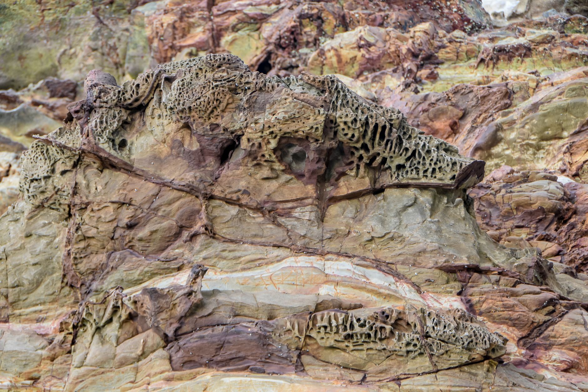
Weathering is the progressive breakdown of rock under the action of physical, chemical, and biological processes at or near the earth’s surface. It reduces the strength of the rock material and the mass, increases porosity and permeability, and changes the colour and mineralogy of the material. BS 5930:2015 defines a six-grade weathering classification for rock, which provides a systematic and reproducible basis for describing the degree to which a rock material has been altered from its original state.
Grade I — Fresh — describes rock that shows no discolouration or change from the original material. Fracture surfaces may show slight discolouration. The rock rings under the hammer and breaks across mineral grains rather than along grain boundaries. Grade II — Slightly weathered — rock shows discolouration particularly along discontinuities, but the rock material itself is largely unaltered. The rock still rings under the hammer. Grade III — Moderately weathered — rock is discoloured throughout and the weaker minerals, particularly feldspars and micas in igneous rocks, may be slightly altered. The rock no longer rings but can still only be broken by the hammer. Grade IV — Highly weathered — rock is discoloured and altered, with significant alteration of the mineral assemblage. The rock can be broken by hand in some cases, and the rock material may be friable. Discontinuities may be infilled with altered material.
Grade V — Completely weathered — describes material that has been altered to the extent that it has the colour, texture, and general character of a soil, but retains the original fabric (structure) of the parent rock. This is the material commonly referred to as “saprolite” or “residual soil” in tropical weathering profiles. It can be broken by hand or with a sharp blow of the geological hammer, and its engineering properties are more akin to those of a soil than a rock. Grade VI — Residual soil — the original rock fabric has been completely destroyed by weathering, and the material is a true soil, typically a clay or silt with no remnant rock structure. This distinction — between Grades V and VI — is important because Grade V material, despite behaving largely as a soil, retains a fabric that may influence its permeability, anisotropy, and failure behaviour.
In practice, weathering is rarely uniform, and rock masses often exhibit zonation of weathering grades, with fresh or slightly weathered rock at depth grading upwards through moderately and highly weathered material to completely weathered rock and residual soil near the surface. Corestones — rounded masses of less weathered rock within a highly or completely weathered matrix — are characteristic of granites and other massive igneous rocks in tropical and subtropical climates, and their presence must be carefully noted in logs, since they can create misleading impressions of rock quality if not properly described.
Fracture Spacing
The spacing of fractures within a rock mass is one of the most important factors controlling its engineering behaviour. A closely fractured rock mass has much lower strength, stiffness, and bearing capacity than a widely fractured one, and is more susceptible to excavation-related instability, water ingress, and time-dependent deformation. BS 5930:2015 defines fracture spacing classifications based on the mean spacing between adjacent discontinuities measured along a scanline perpendicular to the dominant discontinuity set.
The BS 5930 fracture spacing terms are: Very widely spaced (greater than 2000 mm), Widely spaced (600 mm to 2000 mm), Medium spaced (200 mm to 600 mm), Closely spaced (60 mm to 200 mm), Very closely spaced (20 mm to 60 mm), and Extremely closely spaced (less than 20 mm). These terms are directly linked to the Rock Quality Designation (RQD) and to the fracture frequency parameter used in rock mass classification systems. A rock with a very closely spaced fracture system, for example, will typically have a low RQD and a poor rock mass classification, regardless of the strength of the intact material.
In core logging, fracture spacing is assessed from the frequency of natural fractures (as opposed to drilling-induced breaks) along the core. It is essential to distinguish between natural fractures and those caused by the drilling and recovery process — a distinction that is not always easy, particularly in weaker or more fractured materials where the core may have been damaged during drilling. Natural fractures typically have iron-staining, mineral infill, or a rough or irregular surface texture, whereas drilling-induced fractures are often clean, smooth, and oriented at a consistent angle to the core axis.
Discontinuities
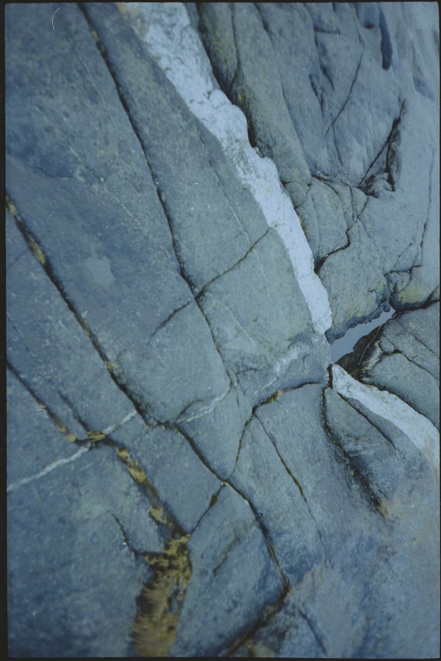
A discontinuity is any plane of weakness within a rock mass — a joint, fault, bedding plane, foliation plane, cleavage plane, or any other structural feature that divides the rock into discrete blocks. The engineering behaviour of most rock masses is controlled by their discontinuities rather than by the strength of the intact rock material, because failure typically occurs along pre-existing planes of weakness rather than through the intact rock. The systematic description of discontinuities is therefore one of the most important aspects of rock logging, and one of the areas where careful, experienced observation makes the greatest difference to the usefulness of the log.
BS 5930:2015 requires that discontinuities be described in terms of a set of standard parameters: type, orientation (dip and dip direction), spacing (as described above), persistence (the length or area over which the discontinuity can be traced), aperture (the width of the opening between the two rock walls), roughness (the small-scale surface texture of the discontinuity walls), infill (the material occupying the aperture, if any), and seepage (the presence and estimated rate of water flow along the discontinuity). Each of these parameters has a defined set of descriptive terms, and the systematic recording of all of them for each significant discontinuity set provides the information needed for rock mass classification and stability analysis.
The orientation of discontinuities is of particular importance for slope stability, tunnel design, and foundation analysis, since the potential for sliding, toppling, or wedge failure depends critically on the angle of the discontinuity relative to the excavated face or the direction of loading. In core logging, orientation can be measured using an orientated core system, which marks the core with a reference line before recovery so that the spatial orientation of discontinuities can be determined from their angle to the reference line. Without orientated core, only the angle of discontinuities to the core axis (the alpha angle) can be measured, which limits the interpretation of structural data.
Infill material within discontinuities is of particular engineering importance. A discontinuity with no infill and rough, interlocking walls will have a high friction angle and significant cohesion; a discontinuity with a thin coating of chlorite or graphite will be much weaker; and a discontinuity infilled with soft clay will have very low strength, with the shear strength approaching that of the clay infill rather than the rock itself. The presence, thickness, and nature of infill must be carefully recorded, and wherever possible, samples of infill material should be collected for laboratory testing.
Strength Descriptions
The strength of intact rock is described using a set of standard terms in BS 5930:2015, each corresponding to a defined range of uniaxial compressive strength (UCS) and assessed in the field by simple index tests. The standard strength terms, from weakest to strongest, are: Extremely weak (UCS 0.25 to 1 MPa), Very weak (1 to 5 MPa), Weak (5 to 25 MPa), Medium strong (25 to 50 MPa), Strong (50 to 100 MPa), Very strong (100 to 250 MPa), and Extremely strong (greater than 250 MPa). These terms apply to the intact rock material tested in the laboratory or assessed in the field, not to the rock mass as a whole.
Field assessment of rock strength relies on simple index tests that can be carried out with no equipment beyond a geological hammer and a penknife. The scratch test involves attempting to scratch the rock surface with a knife blade: extremely weak rock can be scratched with a fingernail, very weak rock can be peeled with a knife, and weak rock can be scratched with difficulty. Medium strong and stronger rocks cannot be scratched by a knife. The hammer test involves striking the rock with a geological hammer and observing the response: very weak rock crumbles under a single blow, weak rock breaks under firm blows, and medium strong and stronger rocks give a ringing sound and only break with heavy blows. These tests are rapid and practical, but they are subject to variability depending on the skill and experience of the logger, and they should always be supplemented by laboratory testing of representative samples.
The point load index test provides a more quantitative field assessment of rock strength. A piece of rock — typically a fragment of core — is loaded between two conical platens in a portable point load testing apparatus until it breaks. The point load index Is(50) (corrected to an equivalent core diameter of 50 mm) can be converted to an approximate UCS using the relationship UCS ≈ 24 × Is(50), though the reliability of this conversion varies between rock types. The Schmidt hammer — a spring-loaded device that measures the rebound of a steel plunger from the rock surface — provides another index of surface hardness, though it is sensitive to the presence of thin weathered coatings and should be used with care.
Producing a good rock log requires the same qualities as producing a good soil log: systematic observation, geological knowledge, and professional discipline. The temptation to use vague or default descriptions — “SANDSTONE, moderately weathered, medium strong” repeated for every run regardless of what is actually in the core — should be resisted. Every significant change in rock type, weathering grade, fracture frequency, or discontinuity character should be captured in the log, because it is these details that will determine whether the ground model is fit for purpose and whether the design based on it is safe and cost-effective.


Leave a Reply