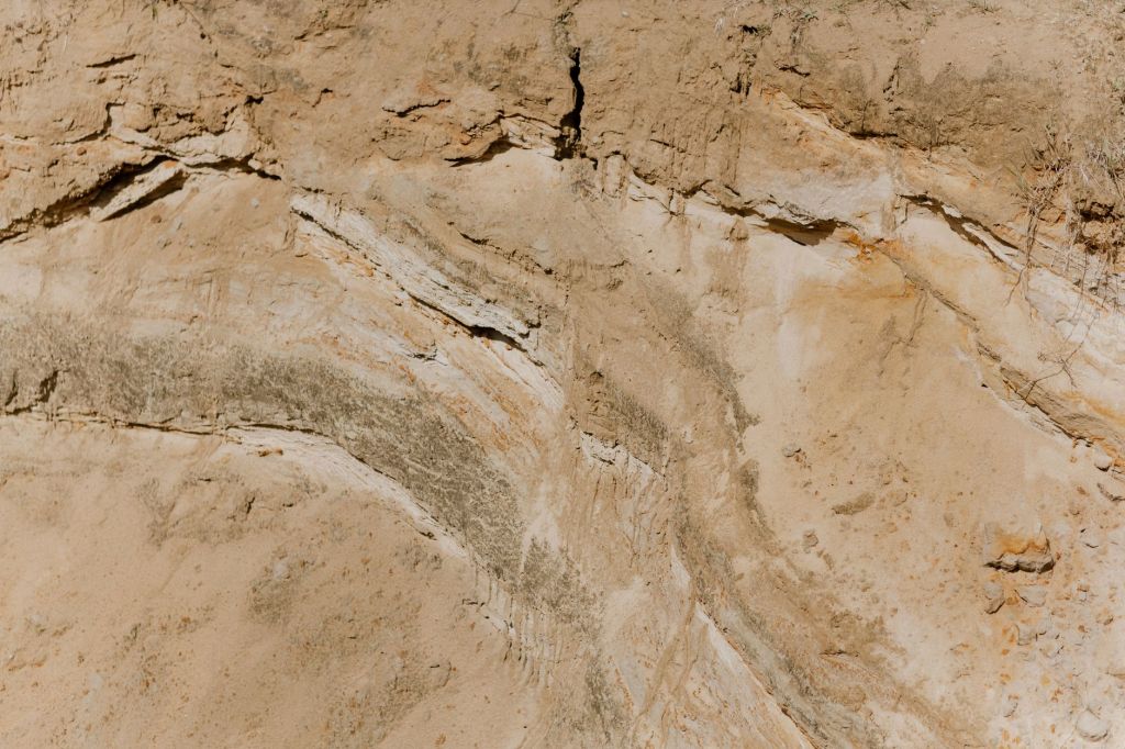
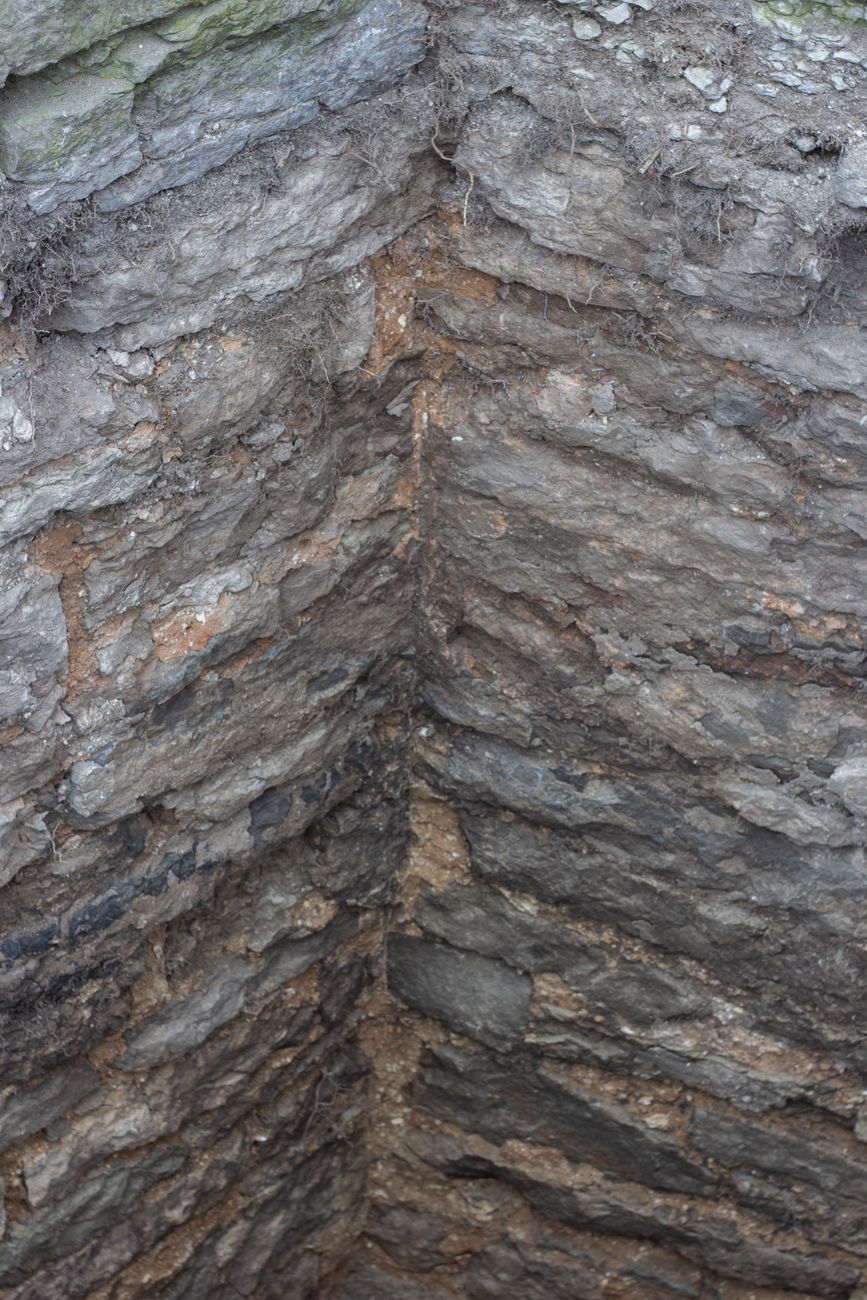
Of all the concepts in geotechnical engineering, shear strength is perhaps the most fundamental. Every failure — every slope that slides, every foundation that sinks, every retaining wall that topples — is ultimately the result of shear stress exceeding shear strength somewhere in the ground. Understanding shear strength means understanding how soils and rocks resist deformation and collapse. Without it, there is no rational basis for designing anything that sits on, in, or alongside the ground. Yet despite its central importance, shear strength is also one of the most nuanced and frequently misunderstood aspects of geotechnical engineering, because it is not a fixed property but one that depends on drainage conditions, stress history, water pressure, and the structure of the soil itself.
The Mohr–Coulomb Failure Criterion
The starting point for understanding shear strength is the Mohr–Coulomb failure criterion, which remains the most widely used model in geotechnical practice despite being well over a century old. It states that the shear stress at failure on any plane is a linear function of the normal stress acting on that plane. The equation is deceptively simple: shear strength equals cohesion plus normal stress multiplied by the tangent of the friction angle. This equation encapsulates the two fundamental mechanisms by which soil resists shear — cohesive bonding between particles and frictional resistance between particles sliding past one another.
The beauty of the Mohr–Coulomb criterion lies in its ability to describe shear strength across a wide range of soils with just two parameters. Its limitation lies in the fact that real soils do not always behave so neatly — the relationship between shear stress and normal stress can be curved, particularly at very low or very high stress levels, and the parameters c and φ are not truly constant properties but depend on the stress level, drainage conditions, and the way the test is conducted. Nevertheless, for most practical purposes, the linear approximation is adequate, and the framework provides engineers with a tractable and physically meaningful basis for analysis.
Cohesion
Cohesion, represented by the symbol c, is the component of shear strength that exists even when the normal stress on a failure plane is zero. In physical terms, it represents the bonding that holds soil particles together in the absence of any confinement. But here is where geotechnical engineering gets complicated: cohesion is not a single, simple material property. It appears in two quite different forms depending on context, and confusing them is a common source of error in practice.
True cohesion arises from genuine inter-particle bonding — cementation by calcium carbonate, iron oxides, or other minerals deposited between particles; the bonding in lightly overconsolidated clays from the rearrangement of clay platelets during consolidation; and the electrostatic and van der Waals forces that hold clay particles together. True cohesion is a fundamental property of the soil fabric and can persist over geological time. Soft rocks, cemented sands, and many residual soils owe much of their strength to true cohesion.
Apparent cohesion, by contrast, arises not from real bonding but from negative pore water pressure — suction — that develops in unsaturated or partially saturated soils when water tension pulls particles together. Dig a sand castle on a beach and it stands firm; let it dry out completely or immerse it in water and it collapses. The cohesion that keeps it standing is apparent cohesion, entirely dependent on capillary suction and therefore vulnerable to changes in moisture content. Apparent cohesion is also the reason freshly excavated clay cuts stand nearly vertically — negative excess pore pressures generated during unloading temporarily increase effective stress and therefore shear strength. As pore pressures equalise over time, the apparent cohesion dissipates and slopes that appeared stable can fail, sometimes years after construction.
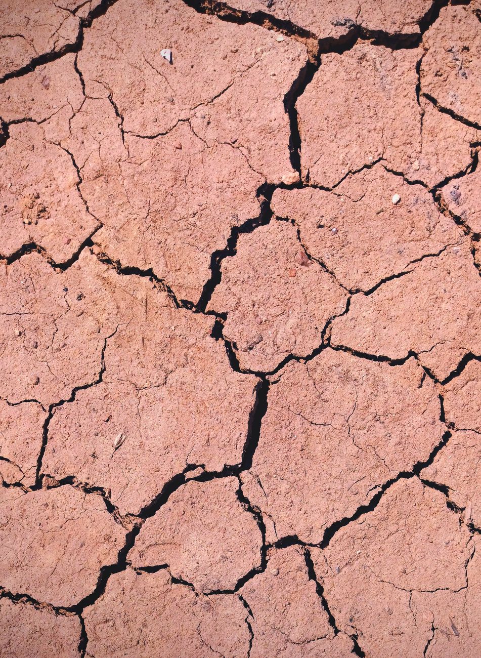
In practice, when engineers refer to an undrained shear strength parameter cu, they are not referring to true cohesion at all — they are treating the total stress shear strength of the soil as a single value that incorporates whatever frictional resistance and pore pressure effects exist at the time of testing. This is a pragmatic approximation, not a statement about the physical nature of the soil, but it is enormously useful in practice for analysing short-term loading scenarios where pore pressures cannot dissipate during the time frame of interest.
Friction Angle
The friction angle φ represents the rate at which shear strength increases with increasing normal stress. It reflects the fundamental mechanism of grain-to-grain friction and interlocking. When two soil particles are pressed together and one slides over the other, energy is consumed in overcoming the friction at their contact points and in pushing particles apart as they ride up over one another — a mechanism called dilatancy. The friction angle is therefore a composite of surface friction at particle contacts and the geometric interlocking that depends on the shape, size, and arrangement of grains.
For clean sands and gravels, the friction angle is largely a function of grain shape and packing density. Angular, well-graded particles that interlock tightly have higher friction angles than rounded, uniformly graded particles that can rearrange more easily. Typical friction angles for sands range from around 28° for loose, rounded sands to 45° or more for dense, angular gravels. Gravels generally exhibit higher friction angles than sands, while silts tend toward lower values due to the dominance of silt-sized particles that offer less interlocking.
For clays, friction angle is a more complex concept. The friction angle of clays is related to the mineralogy of the clay platelets themselves. Kaolinite, a common clay mineral, tends to have relatively high friction angles (around 20–30°) while smectite (montmorillonite), which dominates highly plastic expansive clays, can have friction angles as low as 5–10° at residual strength. This is why landslides in smectite-rich soils can be extraordinarily mobile and persistent — once the clay platelets are aligned along a failure surface and the residual strength is reached, very little shear resistance remains.
The distinction between peak and residual friction angle is critical in practice. The peak friction angle represents the maximum shear stress a soil can sustain before it begins to strain-soften. The residual friction angle is the much lower value reached after large displacements, when all particle interlocking has been destroyed and clay platelets have become fully aligned parallel to the failure surface. Where a pre-existing failure surface is present — as in many natural landslides and some cut slopes in overconsolidated clays — it is the residual friction angle, not the peak, that controls stability. Designing using peak values in such situations is unconservative and potentially dangerous.
Effective Stress
Perhaps the single most important principle in soil mechanics is the concept of effective stress, introduced by Karl Terzaghi in the 1920s and 1930s. Effective stress is the difference between total stress and pore water pressure. It represents the stress that is actually transmitted through the soil skeleton — the contact forces between particles — as opposed to the stress carried by the pore fluid itself.
The insight is profound and not immediately obvious. When a load is applied to a saturated soil, the pore water initially carries much of the load because water is virtually incompressible. As time passes and water drains away, the load is progressively transferred to the soil skeleton, increasing the effective stress and hence the shear strength. Conversely, when water is under positive pressure — as when the water table rises, or when water is trapped in fine-grained soils during rapid loading — it reduces the effective stress and therefore reduces shear strength.
This is why slope failures so often occur during or immediately after periods of heavy rainfall. The rise in groundwater pressure does not add weight to the slope — it reduces the effective stress on potential failure surfaces, diminishing the frictional resistance that holds the slope in place. An apparently stable slope can lose a significant fraction of its factor of safety simply because the water table has risen by a metre or two. Engineers must therefore always think in terms of effective stress when evaluating long-term stability, even when — especially when — they are working with undrained shear strength parameters for short-term analysis.

Undrained vs Drained Behaviour
The distinction between undrained and drained shear strength is one of the most practically important concepts in geotechnical engineering, and one that is frequently misunderstood by those new to the field. The key is recognising that the drainage conditions during loading determine whether pore pressures change, and therefore whether the effective stress and shear strength are the same as, higher than, or lower than they would be under drained conditions.
Drained behaviour occurs when loading is slow enough, or the soil permeable enough, that pore pressures do not build up — any excess pore pressure generated by loading dissipates as quickly as it forms. In drained conditions, effective stress analysis is directly applicable and the long-term shear strength parameters — effective cohesion c’ and effective friction angle φ’ — are the appropriate parameters to use. Coarse-grained soils like sands and gravels nearly always behave in a drained manner under typical engineering loading rates because their high permeability allows rapid drainage.
Undrained behaviour occurs when loading is rapid relative to the drainage rate, so that pore pressures cannot dissipate during loading. In saturated soils, undrained loading occurs at constant volume — the soil does not compress or expand — and the pore pressure change generated by the applied stress can be positive or negative depending on the initial state of the soil. Soft clays and silts under rapid loading are the classic example. When a load is applied quickly to soft clay — a building on soft ground, an embankment built too rapidly, a cut slope excavated too quickly — the clay has no time to drain, pore pressures build up, and the effective stress and shear strength may be much lower than they will eventually be after drainage. Short-term stability is therefore critical in such situations.
The undrained shear strength su (or cu) is not a fundamental property of the soil in the same way that effective friction angle is. Rather, it is an operational parameter that captures the composite behaviour of the soil at a particular stress state and loading rate. Its value depends on the direction of loading (compression, extension, or simple shear), the initial stress state, the stress history of the soil, and the rate of strain. This is why laboratory measurement of undrained shear strength requires careful thought about which type of test is appropriate and how well it replicates the field conditions of interest.
For normally consolidated clays, undrained shear strength typically increases with depth in proportion to the effective overburden stress. The ratio su/σ’v is a useful normalised parameter that reflects the intrinsic shearing resistance of the clay structure, and is typically in the range of 0.2 to 0.3 for many soft clays. Overconsolidated clays — those that have been subjected to greater stresses in the past than they carry today — have higher undrained shear strength relative to their current effective overburden stress, reflecting the denser packing and stronger bonding acquired during their loading history.
Measuring Shear Strength in Practice
Shear strength is measured both in the field and in the laboratory, and the two approaches provide complementary information. In the laboratory, the direct shear test, triaxial compression test, and simple shear test are the most common methods. The triaxial test is arguably the most versatile — it allows drainage conditions to be controlled, pore pressures to be measured, and a wide range of stress paths to be applied. The direct shear test is simpler and quicker but does not allow drainage control or pore pressure measurement, and imposes a fixed failure plane.
In the field, the vane shear test is widely used to measure undrained shear strength in soft clays, particularly offshore. It is quick, simple, and minimises sample disturbance, but measures strength in a particular mode (rotation of a cruciform vane through the clay) that may not be fully representative of all loading directions. The cone penetration test (CPT) and standard penetration test (SPT) provide indirect estimates of shear strength through empirical correlations, and are invaluable for site characterisation even though they do not directly measure shear strength parameters.
No single test is perfect, and good practice involves selecting a testing programme that addresses the specific failure modes relevant to the project, controls drainage conditions to match the field scenario, accounts for anisotropy and stress history, and provides sufficient data to capture spatial variability. Shear strength is not a number to be looked up in a table — it is the result of understanding the soil, the loading conditions, and the engineering problem at hand, and selecting tests that illuminate the behaviour that matters most. It is, in every sense, the foundation upon which geotechnical engineering is built.


Leave a Reply