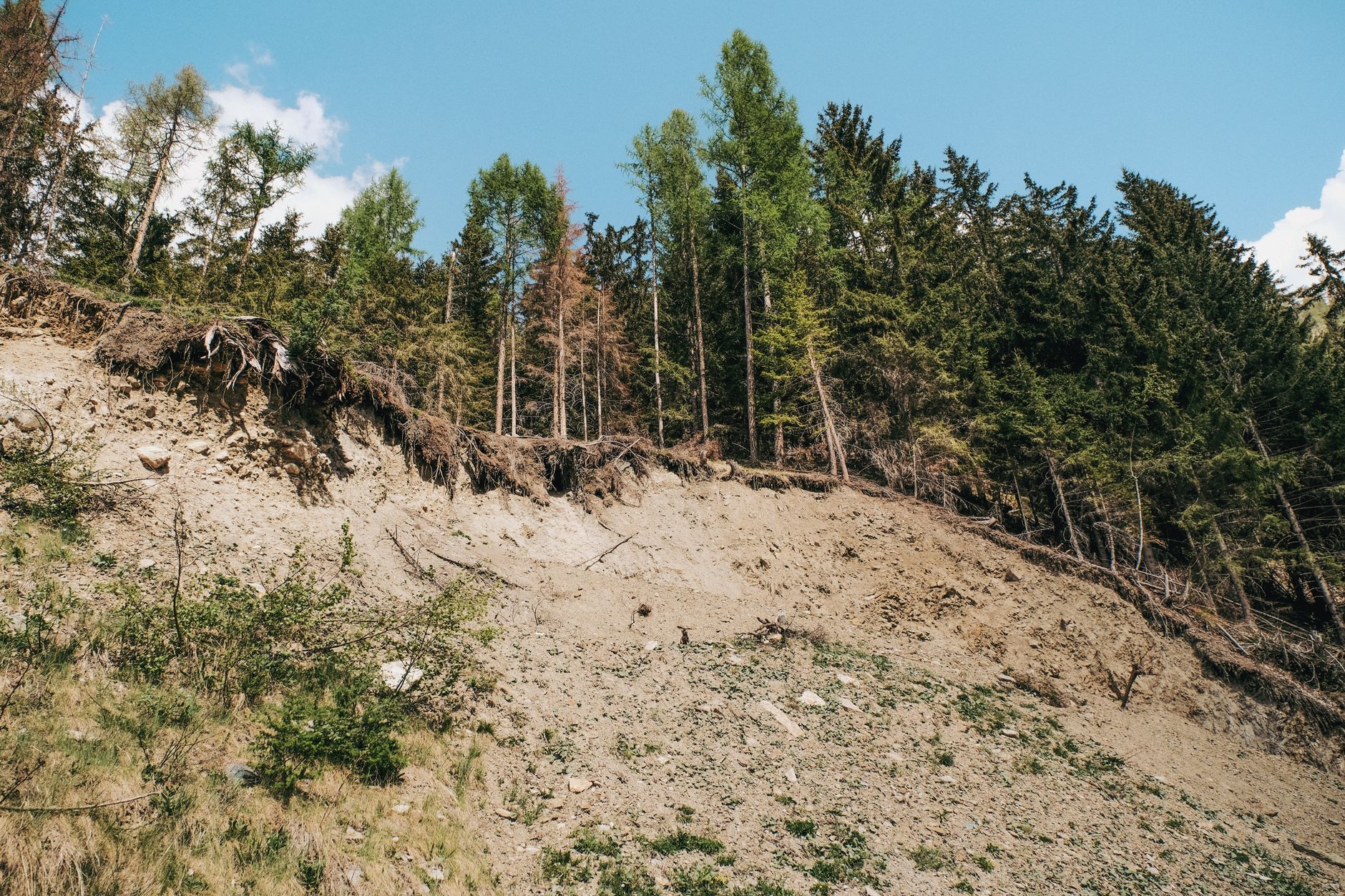
Slopes are everywhere. Natural hillsides carved by erosion, river banks undercut by flowing water, engineered embankments carrying roads and railways, excavated cuts exposing the rock and soil that lie beneath our cities — all of these share a common challenge: the material that forms the slope must resist the tendency to slide downward under gravity. When it cannot, the result is a slope failure, and slope failures are among the most destructive and costly geotechnical hazards in the world. Understanding why slopes fail, how failure occurs, and what engineers can do to assess and improve stability is one of the central disciplines of geotechnical engineering.
Why Slopes Fail
At its most fundamental, slope failure occurs when the shear stress acting along a potential failure surface exceeds the shear strength of the material along that surface. This is the basic limit equilibrium concept that underpins virtually all slope stability analysis. The shear stress is driven by gravity — the weight of the material above the failure surface creates a tendency for that material to slide. The shear strength resists this tendency, and it depends on the cohesion and friction angle of the soil or rock, and on the effective normal stress acting on the failure surface.
Many factors can tip this balance toward failure. Slope geometry is perhaps the most obvious — steeper slopes and taller slopes have greater driving forces. But changes in soil strength or pore pressure are equally important and often more insidious. Rainfall is the most common trigger for slope failures worldwide: as water infiltrates into the slope, pore pressures rise, effective stresses fall, and shear strength decreases — sometimes catastrophically. Rapid drawdown of a reservoir or river can have the same effect, since the water that was providing stabilising pressure against the slope face is removed faster than pore pressures within the slope can drain. Earthquakes, vibration, erosion of the toe, and loss of vegetation cover are other common triggers.
Many slope failures are not sudden events but the culmination of long-term processes. Progressive failure — where peak strength is exceeded locally, driving stress onto adjacent material which then also yields — can cause a slope to fail at a lower average stress than the peak strength of the material. Creep, where the soil moves slowly over months or years without a well-defined failure event, is common in plastic clays. And many catastrophic failures are preceded by small movements that, if monitored, would have provided warning of the impending event.

Circular Failures
In homogeneous soils, particularly soft and medium clays, slope failures tend to occur along curved failure surfaces that are approximately circular in cross-section. This is because the circular shape minimises the energy required to mobilise a given mass of material, and clays — being relatively isotropic and lacking the pronounced discontinuities that characterise many rocks — offer no preferred plane along which failure is more likely to occur.
Circular failure analysis was put on a rigorous footing by the development of limit equilibrium methods in the early to mid-twentieth century. The Swedish slice method (or Fellenius method), developed in the 1920s, was the first systematic approach: the failure mass is divided into vertical slices, equilibrium is assessed for each slice, and the factor of safety is computed as the ratio of the resisting moment to the driving moment about the centre of the assumed failure circle. The method is conservative (it neglects inter-slice forces) but provides a useful starting point.
More rigorous methods — Bishop’s Simplified Method, Janbu’s Method, Spencer’s Method, and Morgenstern-Price — improve on the Swedish slice method by making different assumptions about the inter-slice forces. Bishop’s Simplified Method, which assumes horizontal inter-slice forces, is widely used for circular failures because it gives accurate results for most practical problems while remaining computationally straightforward. Spencer’s Method and Morgenstern-Price satisfy both force and moment equilibrium, giving the most rigorous limit equilibrium solutions for general slip surfaces.
The critical circular failure surface — the one giving the lowest factor of safety — is found by trial and error (or, in modern practice, by optimisation algorithms). Many different circles are analysed, and the critical surface is identified. The factor of safety along this surface is the measure of the slope’s stability, with values above 1.0 indicating stability and values below 1.0 indicating failure.
Planar Failures
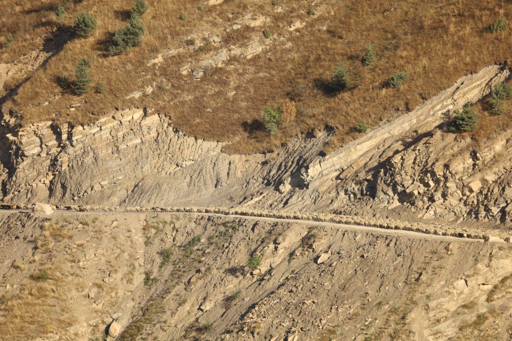
Where distinct planes of weakness exist within the slope material — bedding planes in sedimentary rock, foliation in metamorphic rock, joints or fault planes in any rock type, or layers of weaker material within a soil profile — failure may occur along these pre-existing planes rather than through the intact material. These are planar failures, and they are particularly common in rock slopes and in cut slopes where geological structure is exposed.
The classic planar failure model considers a block of rock or soil resting on an inclined failure plane, with the plane dipping in the direction of potential movement. Failure occurs when the downslope component of the block’s weight (and any other driving forces, such as water pressure) exceeds the frictional and cohesive resistance on the plane. The analysis is straightforward: for a dry slope with no cohesion on the failure plane, failure occurs when the dip of the plane exceeds the friction angle of the material — a simple and elegant result that captures much of the essence of planar failure mechanics.
In practice, planar failures are more complex. Water pressure in tension cracks at the back of the failure block, water pressure on the failure plane itself, the presence of cohesion, and the geometry of the slope face all need to be accounted for. Nevertheless, the basic kinematic condition — that the failure plane must daylight in the slope face (that is, emerge at the surface downslope of the crest) and must dip in the direction of potential movement — provides a powerful screening tool. If a geological structure does not satisfy these kinematic criteria, planar failure on that structure is not possible regardless of the strength parameters involved.

Wedge Failures
In three-dimensional rock slopes, two intersecting planes of weakness can define a tetrahedral wedge of rock that, if the intersection line daylights in the slope face, can slide out of the slope on both planes simultaneously. This is a wedge failure, and it is one of the most common failure modes in rock slopes containing two or more persistent joint sets.
Wedge failure analysis is inherently three-dimensional, and the kinematic assessment requires examining the orientation of the line of intersection of the two planes (the intersection line) relative to the slope face. If the intersection line plunges out of the slope face at an angle less than the slope angle and greater than the friction angle on the planes, wedge failure is kinematically possible. Stereographic projection — using hemisphere projections (stereonets) to plot structural data — is the standard tool for performing this kinematic analysis rapidly for large numbers of geological structures.
The stability of a wedge is assessed by comparing the driving force (the component of the wedge weight acting down the line of intersection) with the resisting forces on the two planes (which depend on the normal force on each plane and the friction angle and cohesion). The analysis is more complex than planar failure because the distribution of normal force between the two planes depends on the geometry of the wedge. Several analytical solutions exist for the factor of safety of a wedge, ranging from simple friction-only analyses to full cohesion-plus-friction analyses with water pressure included.
Factors of Safety
The factor of safety (FoS) is the fundamental metric of slope stability, and understanding what it means — and what it does not mean — is essential for anyone working in slope engineering. In its most basic form, the factor of safety is defined as the ratio of the available shear strength of the material to the shear stress required for equilibrium along the potential failure surface. A factor of safety greater than 1.0 means the slope is stable; less than 1.0 means it has already failed; and exactly 1.0 means it is in a state of limiting equilibrium — on the verge of failure.
The minimum acceptable factor of safety for a slope depends on the consequences of failure, the confidence in the input parameters, and the duration over which the slope must remain stable. For permanent engineered slopes with severe consequences of failure — highway cuttings, dam embankments, retaining structures — minimum factors of safety of 1.3 to 1.5 are typically required. For temporary excavations or situations where failure would cause limited damage, lower values (1.2 or even lower) may be acceptable. For natural slopes where the uncertainty in ground conditions is high, higher factors of safety may be required to compensate.
The factor of safety is, however, a deterministic concept that hides the uncertainty inherent in geotechnical parameters. Soil strength, groundwater conditions, and geological structure all vary spatially and are known only imperfectly. A factor of safety of 1.3 calculated with uncertain parameters provides less actual safety than a factor of safety of 1.3 calculated with well-constrained parameters. This recognition has driven the development of probabilistic approaches to slope stability, where the variability in input parameters is explicitly modelled and the probability of failure is computed rather than (or in addition to) a single factor of safety.
Slope Stability in Practice
Modern slope stability practice integrates geological mapping, ground investigation, laboratory testing, and sophisticated numerical and limit equilibrium analysis. The starting point is always an understanding of the geology — the types and arrangement of materials, the presence and orientation of discontinuities, and the groundwater regime. No amount of sophisticated analysis can compensate for a poor understanding of the ground.
Ground investigation for slope stability typically includes drilling and sampling to characterise the soil and rock profile, in-situ testing to assess strength and stiffness, and installation of piezometers to measure groundwater conditions. Laboratory testing provides the shear strength parameters — peak and residual friction angle, cohesion — that form the inputs to stability analysis. In many cases, back-analysis of existing failures in similar materials provides the most reliable way to calibrate strength parameters.
Slope stabilisation measures range from simple drainage (which reduces pore pressures and increases effective stress) to ground anchors (which provide additional restraining force), to retaining walls, soil nails, rock bolts, and in extreme cases, complete removal and reconstruction. The most effective measure depends on the failure mechanism, the materials involved, and the practical constraints of the site. Drainage is often the most cost-effective first option because it addresses the root cause of many failures — elevated pore pressures — rather than simply adding resistance to an already marginal system.
Slope stability is ultimately a discipline that demands both rigorous analysis and sound engineering judgement. The ground is complex, variable, and imperfectly known, and the consequences of slope failure can be catastrophic. The combination of thorough site investigation, appropriate analysis methods, conservative strength parameters, adequate factors of safety, and ongoing monitoring is what separates well-designed slopes from those that fail unexpectedly. In slope engineering, as in all of geotechnics, the quality of the ground model — the engineer’s understanding of what is actually in the ground — is the most critical determinant of a safe design.


Leave a Reply