
Quarry face and slope geometry is, in a great many operations, set by generic and precedent-based rules of thumb: a single batter angle carried across the whole excavation, a standard ten-metre bench, a fixed berm width. These templates are simple to communicate and to supervise, and they are usually safe. They are also, in most competent rock, unnecessarily conservative — and that conservatism has a direct and permanent cost. Every degree by which a face is flattened beyond what the geology requires pushes the toe of the slope inward and sterilises a wedge of mineral that sits within a hard-won, planning-consented boundary. That mineral is not deferred. It is lost.
This post sets out the technical and regulatory basis for a different approach: bespoke, structurally-controlled face design driven by site-specific measurement of discontinuity dip and strike. The argument covers the regulatory framework, the structural geology that governs stability, the measurement and analysis methodology, the mineral recovery case, the safety framework, and the broader economic and social value of getting this right.

The Regulatory Context: a Standard Design is a Habit, Not a Requirement
The relevant duties sit in Part VI of the Quarries Regulations 1999 (SI 1999/2024). In outline, Regulation 30 places a general duty on the operator to ensure that excavations and tips are stable and do not endanger health and safety. Regulation 31 requires site-specific Excavations and Tips Rules. Regulation 32 requires appraisal by a competent person to determine whether a significant hazard is present. Regulations 33 and 34 define the geotechnical assessment and geotechnical specialist, and require assessment at intervals not exceeding two years for notifiable features — and sooner where conditions change.
The essential character of these provisions is that they define a process and a standard of care, not a product. They require that a design exists, that it is the work of competent and suitably specialised persons, that it is evidenced and embedded in the Excavations and Tips Rules, and that it is kept under review as the excavation develops. They do not specify a face angle, a bench height, a berm width, or an overall slope angle. That is a deliberate feature of goal-setting health and safety law.
The Approved Code of Practice L118 accompanies the Regulations. An ACOP has special legal standing: a duty-holder who has not followed its relevant provisions and is prosecuted must show that the law was complied with by equally effective means. But the ACOP too is framed around process and adequacy of design rather than prescribed geometry. Industry guidance published through QNJAC reinforces the point: face design is a process, not a product. It is the rigour and traceability of the design process — updated as the geology becomes better understood — that demonstrates compliance and good practice. A design fixed at the outset and never revisited is neither optimal nor, in spirit, what the framework intends.
It follows that the blanket batter angle so often treated as the standard quarry design has no basis in the Regulations. It is a convention: sometimes the residue of a precautionary early assessment, sometimes a figure carried across from a neighbouring operation, sometimes simply the angle that has always been used. None of these is an engineering justification. The Regulations ask a more demanding and more useful question — what does the stability analysis of this rock mass, on this face, support? — and a bespoke, structurally-controlled design is the direct answer to it.
Why Discontinuities, Not Intact Strength, Govern Stability
In strong, competent rock — the sandstones, gritstones and limestones typical of hard-rock quarrying — the intact material is generally far stronger than any stress the slope imposes on it. Failure rarely occurs through fresh fracture of intact rock. It occurs by movement along pre-existing planes of weakness: the discontinuities that pervade every rock mass. The stability of a face is, in consequence, a question about the geometry and strength of those discontinuities and their orientation relative to the excavated surface, far more than a question about the rock’s compressive strength. This is the single most important idea in rock slope engineering.
The discontinuities that matter fall into a few families. Bedding planes are the depositional layering of sedimentary rock and are often the most persistent and continuous surfaces present, frequently with the lowest shear strength. Joints are fractures along which there has been no appreciable displacement; they typically occur in systematic sets of sub-parallel planes, and most rock masses contain two, three or more such sets in consistent orientations. Faults are fractures across which displacement has occurred, often associated with zones of sheared or weakened rock. Each of these has a characteristic orientation, persistence, spacing, roughness, aperture, infill and seepage condition — the parameters that measurement and analysis must capture.
The orientation of any planar discontinuity is described completely by two measurements. Strike is the compass bearing of a horizontal line drawn on the plane. Dip is the maximum angle of inclination of the plane below horizontal, measured in the vertical plane perpendicular to strike; the direction in which that steepest slope descends is the dip direction, always at ninety degrees to strike. In modern practice orientation is recorded as dip/dip-direction — for example 35°/290° — which is unambiguous and feeds directly into stereographic analysis. A distinction that matters on site is between true dip and apparent dip: the inclination seen on an arbitrary face is generally an apparent dip, flatter than the true dip, unless the face is cut perpendicular to strike. All measurements must be referred to true orientation.
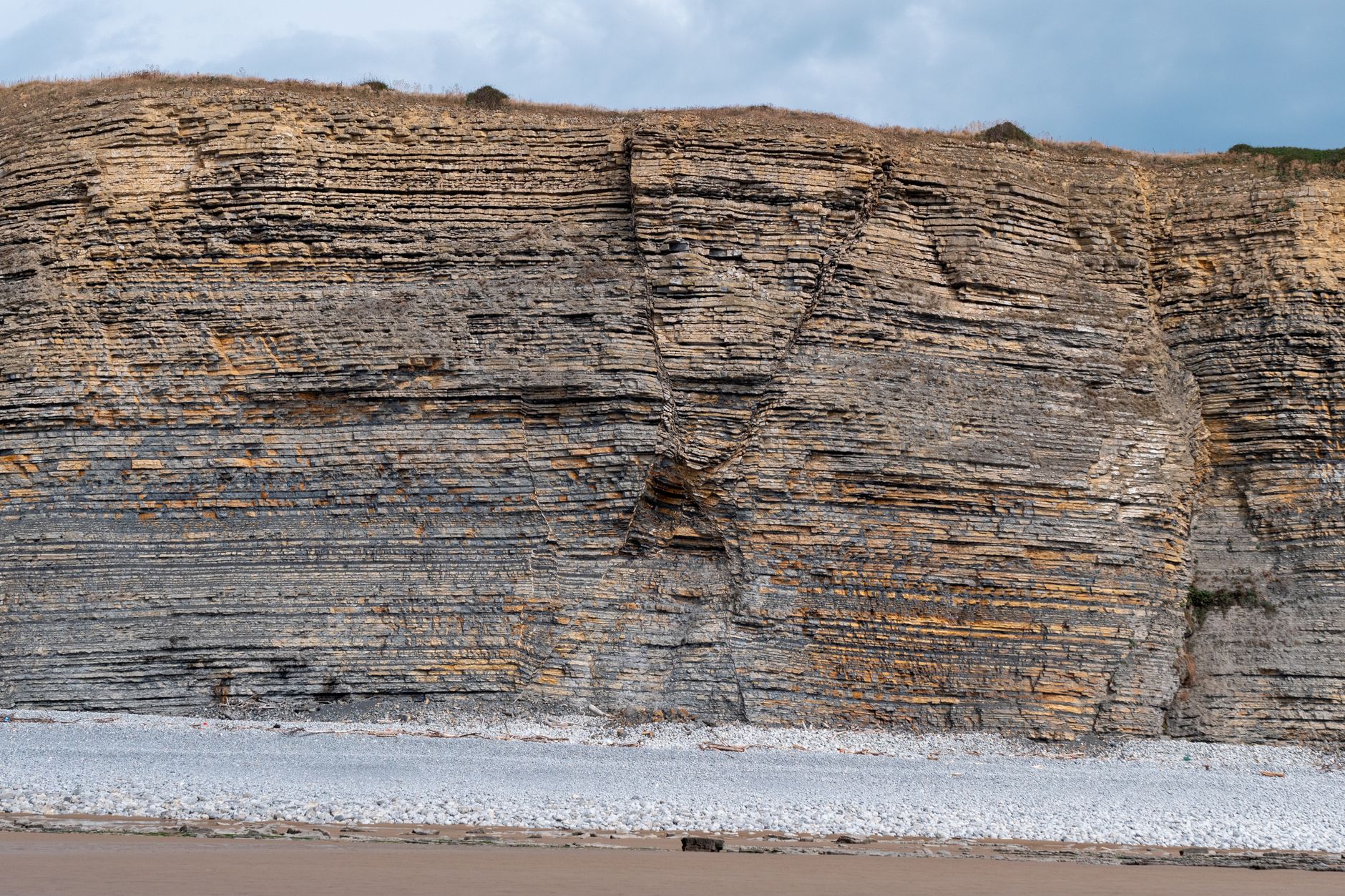
Orientation-Dependent Failure Modes
Each mode of structurally-controlled failure is only possible within a specific geometric relationship between the discontinuities and the face. There are four modes of practical concern.
Planar sliding occurs when a discontinuity daylights in the face — that is, it dips out of the face at an angle less than the face angle but greater than its own friction angle — and its dip direction lies within roughly ±20° of the dip direction of the face. All of these conditions must be met simultaneously; remove any one and planar sliding on that plane is not kinematically possible.
Wedge sliding occurs where two discontinuities intersect and the line of their intersection daylights in the face, plunging out of it at an angle greater than the friction angle but less than the apparent face angle in the direction of the intersection. Wedges can form on faces where no single plane would slide, which is why sets must always be analysed in combination as well as individually.
Toppling occurs where steeply-dipping discontinuities dip into the face, dividing it into columns or slabs that rotate forward under their own weight. It requires that inter-layer slip can occur and that the columns are slender enough to overturn. Toppling is distinctive because it is favoured by the opposite orientation to sliding — planes dipping into the face rather than out of it — which is precisely why a single blanket angle cannot be optimal for all aspects.
Rockfall and ravelling is the release of individual blocks or fragments defined by intersecting discontinuities, driven by weathering, blast damage, water, freeze-thaw and undercutting. It is managed principally through face angle, scaling, catch benches and berm width, and controlled standoff.
The Same Rock, Different Faces
The practical corollary is the crux of the whole argument. Consider a rock mass with a single dominant bedding orientation dipping 35° towards the north. A face on the southern side of the quarry — a north-facing wall into which the beds dip — is highly stable against sliding; the beds hold the face and it can be cut steep and tall, limited chiefly by toppling and rockfall considerations. The opposite wall on the northern side — a south-facing wall out of which the same beds daylight — is exposed to planar sliding and must be cut flatter, or the bedding supported, or the face reoriented.
It is the identical rock mass, the identical bedding, the identical strength. Only the aspect of the face has changed, and with it the entire stability picture. A blanket angle set to be safe on the adverse southern wall is needlessly, and expensively, flat on the favourable one. This is not an edge case; it is the normal condition of a jointed, bedded rock mass, and it is the mineral-recovery opportunity that bespoke design exists to capture.
Real quarries are rarely as tidy as a single bedding orientation. Folding, faulting and lateral variation mean that discontinuity orientations change across the site. The organising concept that makes design tractable is the structural domain: a volume of the rock mass within which the discontinuity sets are sufficiently consistent in orientation and character to be treated as uniform for design. Fold limbs, fault-bounded blocks and lithological units commonly define domain boundaries. Design proceeds domain by domain — each with its own set orientations, its own kinematic assessment, and therefore its own optimal face orientations and angles. The output is not one number for the quarry but a small family of designs mapped onto the plan, each justified by the structure it governs.
Measuring the Structure: Methodology and Standards
The objective of structural characterisation is a defensible, statistically robust description of the discontinuity sets in each domain: their mean orientations, the dispersion about those means, their spacing and persistence, and their shear-strength-relevant properties. A design that steepens a face rests entirely on the quality of the orientation data beneath it, so the data must be gathered to a recognised standard, in sufficient quantity, and corrected for the biases inherent in how it is collected. The ISRM Suggested Methods provide the reference framework for the parameters to record: orientation, spacing, persistence, roughness (quantified through joint roughness coefficient), wall strength, aperture, infill, seepage and degree of weathering.
The traditional and still indispensable tool is direct measurement on the exposure with a compass-clinometer. Two systematic techniques structure the collection. In scanline mapping, a tape is fixed along the face and every discontinuity intersecting it is logged with its orientation and ISRM parameters. In window mapping, a defined area of face is characterised in the same way. Both impose the discipline of complete, systematic sampling in place of the natural tendency to record only the obvious or accessible features. For each set, at least thirty to fifty measurements are needed for the statistics to stabilise so that the mean orientation and its Fisher concentration are reliable rather than the product of a handful of readings.
All line and surface sampling is biased by orientation. A scanline preferentially intersects discontinuities perpendicular to it and systematically under-samples those running sub-parallel — and it is often a sub-parallel, under-sampled set that controls stability. The Terzaghi correction applies a weighting based on the angle between each discontinuity and the sampling line to recover an unbiased estimate. Omitting it can hide the very set that governs the design. The same principle argues for mapping on more than one face orientation so that no set is systematically missed.

UAV photogrammetry and terrestrial LiDAR have transformed structural mapping and should now be regarded as core rather than novel. Structure-from-motion processing of UAV imagery into a dense, scaled and georeferenced three-dimensional point cloud allows discontinuity orientations to be extracted by fitting planes to the surface in software such as CloudCompare. The advantages are substantial: measurement is made at safe standoff, removing the need to work at the toe of a potentially unstable face; coverage extends to upper parts of high faces inaccessible to hand measurement; data density rises by orders of magnitude; and repeated surveys enable movement detection by differencing successive point clouds. The limitations must be respected — surfaces sub-parallel to the line of sight are poorly resolved, reintroducing orientation bias, and automated plane extraction should always be validated against hand measurements. Used together, conventional and digital methods are complementary: the compass-clinometer provides ground truth and the roughness, infill and seepage detail that a point cloud cannot; the digital survey provides the density, reach, safety and repeatability that hand mapping cannot.
The measurements are assembled into a structural model on the stereonet — an equal-area, lower-hemisphere projection. Each discontinuity plots as a pole; the population of poles is contoured to reveal clusters corresponding to sets; and each set is characterised by its mean orientation and dispersion. Where block size, persistence and connectivity matter, the data can be taken further into a discrete fracture network (DFN), a stochastic three-dimensional representation of the discontinuities. The deliverable from this stage is, for each domain, a compact and quantified description of the sets that analysis then turns into a face design.
Kinematic and Stability Analysis
Kinematic analysis asks a purely geometric question: given the set orientations in a domain and a trial face orientation and angle, is each failure mode geometrically possible at all? It is performed on the stereonet and is the natural first filter. A mode that is kinematically infeasible cannot occur however weak the rock, and a face designed so that the dominant modes are infeasible is stable by geometry rather than by a computed margin. The classic construction is the Markland test for planar and wedge sliding, in which the pole of the plane (or the intersection of two planes) is examined against the face great circle, a friction cone of radius equal to the friction angle, and the lateral limits of ±20° for planar release. Analogous constructions test toppling.
To make the logic concrete, take a single illustrative domain in a bedded sandstone with three sets: bedding (Set B) at 38°/010°; a steep joint set (Set J1) at 82°/100°; and a second steep set (Set J2) at 78°/265°. The measured friction angle along the discontinuities is 34°.
A face on the northern side of the quarry cut to face south has the bedding dipping into it. The bedding cannot daylight, so planar sliding on the most persistent set is kinematically impossible whatever the face angle. No steep set dips out towards the south at an orientation generating adverse toppling, and the steep joints strike such that no adverse wedge daylights in a south-facing wall. This face is favourable and can be cut steep — a bench face angle of 70–75° is defensible — with the design governed by rockfall management and blast control rather than any sliding mechanism. This is where mineral is recovered.
The opposite face on the southern side, cut to face north, has the same bedding dipping out of it at 38°, its dip direction aligned with the face. Because the friction angle (34°) is less than the bedding dip (38°), and the bedding daylights below any reasonable face angle, planar sliding on bedding is kinematically feasible and must be quantified by limit-equilibrium analysis. The design response is to flatten the face towards the bedding dip, drain it, support or dowel the bedding, or reorient the working face away from this adverse aspect. A single blanket angle applied to both walls would either sterilise the favourable face or leave the adverse one under-designed — the precise failure that domain-based design removes.
Where a mode is kinematically feasible and must be quantified, limit-equilibrium analysis computes a factor of safety — the ratio of resisting to driving forces along the failure surface. Planar and simple wedge cases have well-established closed-form solutions, evaluated in tools such as RocPlane and Swedge. More general cases are handled by two-dimensional limit-equilibrium or, for large, complex or step-path failures, by numerical distinct-element modelling (UDEC, 3DEC). The strength inputs are the shear strength of the discontinuities — expressed as a Mohr-Coulomb cohesion and friction angle, or through the Barton-Bandis criterion that captures roughness and wall-strength dependence — together with water pressure, any tension crack geometry, and, in some settings, seismic loading. Water is almost always the dominant and most uncertain driver and warrants conservative treatment, drainage where practical, and piezometric monitoring on critical faces.
A face is designed to an explicit acceptance criterion. In deterministic terms this is a target factor of safety, and the target is higher where consequences and exposure are greater: short-term or working faces are frequently designed to around 1.3, and long-term or final faces to around 1.5. The probabilistic frame — increasingly favoured — maps the statistical dataset directly onto a probability of failure, making the effect of orientation scatter explicit. Open-pit design guidance (Read and Stacey, 2009) tabulates acceptable combinations of factor of safety and probability of failure against slope scale and consequence. The analysis yields, for each domain, a complete face design: bench face angle, bench height, catch-berm width, the resulting interramp and overall slope angles, and the accompanying specification for scaling, support, blasting control and monitoring, together with an explicit statement of residual risk.
The Recovery Case: Geometry, Numbers and Scale
The connection between slope angle and mineral recovery is a matter of simple geometry. For a slope of vertical height H between a fixed crest at the permitted boundary and a fixed floor, the horizontal distance from crest to toe is H ÷ tan ψ, or H × cot ψ. Steepening the slope from angle ψ₁ to a steeper angle ψ₂ reduces that horizontal run and advances the toe outward into the deposit. The additional recovered volume over a strike length L of the sector is:
ΔV = ½ · H² · (cot ψ₁ − cot ψ₂) · L
Two features of this expression drive its significance. First, the dependence on the square of the slope height means the prize grows rapidly with the depth of the quarry — deep faces are where the recovery opportunity concentrates. Second, multiplication by the full strike length means a gain calculated per metre of face applies along the entire length of every face in the domain.
Taking an illustrative competent-sandstone sector with a face height of 60 m, a strike length of 400 m, and an in-situ bulk density of 2.55 t/m³, with an inherited generic overall slope angle of 45°, steepening to 50° recovers approximately 295,000 tonnes; to 55° approximately 550,000 tonnes; and to 60° approximately 776,000 tonnes — all relative to the 45° base case, from a single sector alone.
The overall slope angle is not chosen directly; it emerges from the bench-scale design. For a multi-bench slope the interramp angle is governed by three parameters: bench height, bench face angle, and catch-berm width. Steepening the bench faces, increasing the bench height, or narrowing the berms — each only where the structure and rockfall analysis permits — all steepen the interramp angle. Comparing an inherited generic design (10 m bench, 60° face, 5 m berm, interramp angle ~43°) against a structurally-optimised design (15 m bench, 70° face, 4 m berm, interramp angle ~58°) illustrates the available lever. The bespoke figures are achievable only on domains where kinematic and limit-equilibrium analysis supports them; adverse domains are designed flatter.
Feeding those two interramp angles into the recovery geometry for the same 60 m × 400 m sector: moving from 43° to 58° recovers on the order of 320,000 m³ — approximately 820,000 tonnes — of mineral that the generic design would have permanently sterilised. At a modest sector output of 80,000 m³ per year, that is around four additional years of reserve life from this one sector. Applied across the several favourable faces of a working quarry, the cumulative extension runs to a decade or more, without acquiring, permitting or opening any new ground.

Two levers deserve particular emphasis. Increasing the working bench height, where excavator reach and structural stability allow, reduces the number of catch benches over a given slope height. Since each berm consumes horizontal run and holds the toe back, fewer and taller benches steepen the effective slope and recover mineral, while also reducing the total length of berm that must be formed, scaled and maintained. Reducing the number of benches is the same lever from the other side: catch benches exist to arrest rockfall and provide access, and where a domain’s structure genuinely does not generate significant rockfall, an unnecessary catch bench is pure sterilisation. The discipline is to retain catch provision precisely where the rockfall and structural analysis shows it is needed, and to remove it only where that analysis shows it is not.
For crushed-rock aggregate at an illustrative gate value of around £12 per tonne, the roughly 820,000 tonnes of that single sector represents on the order of £10 million of in-ground value — recovered without any new planning consent. For higher-value products such as dimension or block stone, the same recovered volume represents value measured in the tens of millions. The single-sector figure understates the opportunity across a whole quarry, compounded over its remaining life, by an order of magnitude.
Safety, Stability and Risk: Steeper Where Justified is Not Less Safe
The instinct that a steeper face is a more dangerous face is understandable but, applied indiscriminately, it is both technically wrong and commercially costly. A blanket angle offers a uniform assurance that is, in truth, uneven: it is over-cautious on the many faces where the structure is favourable, and it can be dangerously blind on the occasional face where a single adverse discontinuity daylights, because the blanket angle was never derived from that structure and cannot respond to it. Structurally-controlled design inverts this. The adverse plane that a blanket approach might never identify is exactly what kinematic analysis is built to find.
Where analysis identifies feasible failure modes or chronic rockfall, the design manages them through an explicit hierarchy of controls. Scaling removes loose material after excavation and blasting. Rock bolts and dowels secure identified blocks and slabs where support is more economic than flattening. Catch benches and berms, sized to modelled rockfall runout rather than to a fixed width, arrest falling material; catch fences and toe bunds supplement them where the geometry demands. Controlled blasting — pre-split or trim blasting on final and long-term faces — preserves the integrity of the rock behind the face. The importance of controlled blasting is hard to overstate: poor blasting degrades a carefully designed face and can negate the stability the design assumed. Exclusion zones and disciplined standoff keep people away from the hazard while it is being managed.
A steepened design is validated in service by monitoring proportionate to the hazard. On modest faces this may be periodic visual inspection and survey; on higher or more critical faces it extends to prism or robotic total-station monitoring, ground-based interferometric radar for full-face displacement fields, crack meters across identified features, and piezometers where water pressure governs. Repeat photogrammetry or laser scanning doubles as a movement-detection tool through cloud-to-cloud differencing. Monitoring is only useful if it is coupled to a Trigger Action Response Plan (TARP): predefined displacement or rate thresholds, each tied to a defined response from heightened inspection through to evacuation and cessation of work, with clear ownership and escalation. The TARP converts data into decisions and is the mechanism by which a design that pushes the geometry harder remains safe if the ground behaves other than predicted.
The governance wrapper is provided by the Regulations themselves. The competent person’s appraisal under Regulation 32 determines significant-hazard status; the geotechnical specialist’s assessment under Regulations 33 and 34 embodies the bespoke design; the Excavations and Tips Rules under Regulation 31 translate it into operating controls; and the not-more-than-two-yearly reassessment keeps the design current. Because a quarry exposes more of itself as it is worked, this cadence is not bureaucratic overhead but the natural rhythm of a design that improves with data.
Bespoke design and progressive excavation together are a near-perfect fit for the observational method recognised in Eurocode 7: a design based on the most probable conditions, bounded by the range of possible behaviour, with monitoring in place and pre-agreed contingency actions ready if behaviour approaches the bounds. Each newly-cut face is a test of the model that designed it. Where the exposed structure matches prediction, confidence and the design are confirmed. Where it departs, the design is adjusted within the contingencies before the departure becomes a hazard. This is how a quarry can be worked closer to the true structural limit of its rock without working beyond it — by measuring, predicting, verifying and adjusting in a continuous loop.
Longevity, Economic and Social Value
The most direct benefit is reserve life. Mineral recovered from within the existing consent by steepening favourable faces adds working years without any of the cost, delay or uncertainty of extending laterally or opening a new site. Across the UK the trend in permitted aggregate reserves has been broadly downward, with replenishment of permissions lagging extraction and lead times for new or extended permissions measured in years. In that context, mineral left in the ground inside an existing consent is among the most valuable and least replaceable material an operator holds. Sterilised mineral — material within the permitted boundary and below the permitted depth but left unexcavated because the slope above it was cut too flat — is therefore a peculiarly avoidable loss.
Extended reserve life sustains employment. The direct quarry workforce is only the visible part: haulage, plant maintenance, processing, laboratory and technical services, and the downstream operations that consume the output all depend on continuity of supply. Extending the life of a quarry by years preserves those roles and the local supply chains and skills that cluster around a long-lived operation.
Aggregates are low in value and high in bulk, which makes them acutely sensitive to transport cost and distance. Haulage can rival extraction in its contribution to delivered price and to carbon. Extending the life of a well-located quarry therefore preserves not just a volume of rock but a source of local supply, keeping haul distances short for the markets it serves. Premature exhaustion of a local source shifts demand to more distant quarries, raising both cost and transport emissions for every tonne thereafter.
The sustainability case reinforces the commercial one. Recovering a higher fraction of a consented deposit is, straightforwardly, more efficient use of a finite natural resource and of the land already committed to extraction. It reduces the total land-take of mineral working for a given output by deferring new sites and reduces transport emissions by keeping supply local for longer. Better structural understanding also improves final-landform and restoration planning: the geometry of the final faces can be designed with their long-term stability and intended after-use in mind from the outset, rather than inherited from a working geometry chosen for other reasons.
Financially, earlier and greater recovery improves the net present value of an operation, and a better structural and geotechnical dataset improves the confidence with which mineral resources and reserves can be classified and reported. Recovery estimates resting on demonstrated, analysed slope geometries are more defensible than those resting on a precautionary blanket angle, and the reduction in geotechnical uncertainty feeds directly into the confidence categories used in resource and reserve reporting. The same investment in structural characterisation that unlocks the mineral also strengthens the valuation of the asset that contains it.
Limitations, Caveats and Good Practice
The case set out here is deliberately bounded, and the boundaries are as important as the argument.
This methodology is not a licence to over-steepen. It exists to find the correct angle, and on adverse domains that angle is flatter than a careless blanket figure. Any application that only ever steepens has misunderstood the method. Reliability follows data quality and quantity: a steepened design rests on the orientation dataset beneath it, and sparse, biased or unvalidated data cannot support an aggressive geometry. Where data are thin, the design must be conservative, or more data gathered before steepening.
Models simplify. Kinematic and limit-equilibrium methods assume idealised planes and mechanisms. Large, interacting, step-path or deformation-controlled failures require numerical modelling, and the choice of method must match the mechanism and the consequence. Water is the dominant uncertainty: groundwater pressure is usually the largest and least well-known driver of instability, and it warrants conservative assumption, drainage where practical, and piezometric monitoring on critical faces.
Working faces are not final faces. Short-term working geometries and long-term or final geometries are different designs with different exposure durations, different degradation and different acceptance criteria. A working angle must never be left as a final face by omission. Time degrades rock: weathering, freeze-thaw, stress relief, blast damage and time-dependent strength loss all act to reduce stability after excavation, and the design horizon must account for them.
Competence and traceability are mandatory. The work must be done, and be seen to be done, by a geotechnical specialist as defined in Regulation 33, with an auditable trail from measurement through analysis to design and into the Excavations and Tips Rules, and kept under review. The approach also interacts with other constraints: hydrogeology, environmental permits, restoration obligations and planning conditions may all constrain the geometry independently of stability, and the design must reconcile them.
Conclusions and Recommendations
The stability of a quarry face in competent rock is governed by the orientation of its discontinuities relative to the face, not by the strength of the intact rock. Because those orientations vary systematically around a quarry, a single blanket face angle is necessarily wrong almost everywhere: over-flat and wasteful on the many favourable faces, and potentially blind to the adverse plane on the few unfavourable ones. The Quarries Regulations 1999 and ACOP L118 neither require nor endorse a blanket design; they require a reasoned, evidenced, specialist design kept under review, and a bespoke, structurally-controlled approach is that requirement met properly.
The reward is substantial and quantifiable. Putting the correct angle on each domain — steep where the structure is favourable, flat where it is adverse — recovers on the order of 820,000 tonnes of otherwise-sterilised mineral from a single 60 m sector, extending reserve life by years per sector and by potentially a decade or more across a quarry. And it does so at an equal or improved standard of safety, because a design derived from the actual structure locates and controls hazard where it exists rather than papering over it with a uniform angle.
The practical recommendations flow directly from the analysis. Domain-based structural mapping — combining compass-clinometer scanline and window mapping with UAV photogrammetry and/or LiDAR, recording full ISRM parameters and correcting for orientation bias — should be standard across hard-rock sites. Kinematic and limit-equilibrium analysis, with probabilistic analysis where scale or consequence warrants, should be embedded in every Regulation 33/34 geotechnical assessment, designed per structural domain rather than per quarry. Short-term working faces and long-term or final faces should be designed separately, each against an explicit and documented acceptance criterion. Controlled blasting on final and long-term faces should be specified as part of the stability design, not as an afterthought. Monitoring and a Trigger Action Response Plan, proportionate to each face’s hazard, should be implemented and the observational method adopted so that each newly-exposed face validates or refines the design. The domain-specific geometries and controls should be reflected in the Regulation 31 Excavations and Tips Rules, and the design kept under the statutory review cadence as excavation exposes new structure.
The governing principle throughout is the one this whole argument turns on: a quarry face should be no flatter and no steeper than the geology justifies. Establishing what the geology justifies — by measurement, by analysis, and by disciplined review — is the whole of the task, and it serves recovery and safety at the same time.


Leave a Reply