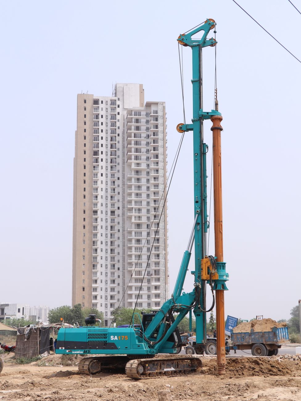
Every structure, however modest or ambitious, depends on the ground beneath it to carry its weight safely and without excessive movement. The foundation is the interface between structure and ground, and choosing the right type is one of the most consequential decisions a designer makes, shaping cost, programme, and risk for the rest of the project. This post works through the basic foundation types encountered on almost every site: strip foundations, pad foundations, raft foundations, piled foundations, and, where none of these are viable without help, ground improvement.
Strip Foundations
A strip foundation is a continuous strip of concrete laid beneath a load-bearing wall, spreading the wall’s line load over a width of ground wide enough to keep the bearing pressure within safe limits. It is the default foundation type for most low-rise masonry construction, particularly domestic housing, because it is simple to design, straightforward to construct, and economical where ground conditions are reasonably uniform and the loads involved are modest. The width of the strip is sized from the allowable bearing pressure of the founding soil and the load per metre run of wall; the depth is governed less by bearing capacity and more by the need to found below the zone of ground affected by seasonal moisture change and frost.
That seasonal zone matters enormously in shrinkable clays, where the ground swells when wet and shrinks when dry, and where mature trees can desiccate the clay around their root system to a depth of several metres. Foundations founded too shallow in such ground can experience significant seasonal heave and shrinkage, or long-term subsidence as a nearby tree matures and its root system extends beneath the foundation. Depths of a metre or more are common in the UK for exactly this reason, and where trees are present or have recently been removed, specialist advice on founding depth is essential.
A variant known as trench fill dispenses with the formwork and reinforcement of a traditional strip, instead filling the entire trench with concrete up to close to ground level. This is faster and often safer to construct, since workers spend less time inside a deep, unsupported trench, though it uses considerably more concrete. Strip foundations of either type are not well suited to heavy or concentrated point loads, to poor or highly variable ground, or to situations where significant differential settlement between different parts of a structure is likely; in those cases, other foundation types take over.

Pad Foundations
A pad foundation, also called a spread footing, is an isolated block of reinforced concrete placed beneath a single point load, typically a steel or concrete column. Rather than spreading load along a line as a strip does, a pad spreads it out in two directions, and its plan dimensions are sized so that the bearing pressure transmitted to the ground stays within the allowable value for the founding material at that depth. Pad foundations are the natural choice for framed buildings, where the structure’s weight is concentrated at discrete column positions rather than distributed along continuous walls.
Sizing a pad is not simply a matter of dividing load by allowable pressure. Where columns are closely spaced, the zone of stressed ground beneath one pad, sometimes visualised as a bulb of pressure extending downward and outward from the base, can overlap with the zone beneath a neighbouring pad, increasing settlement beyond what either pad would experience in isolation. Eccentric loading, from a column that also carries a significant moment, requires either a larger pad to keep the resulting pressure distribution within acceptable limits, or a combined footing that ties two or more columns together on a single larger base.
Differential settlement between pads, rather than the total settlement of any single pad, is often the more critical design consideration for framed structures, since a structural frame is generally far more tolerant of uniform movement than of one column settling noticeably more than its neighbours. Ground beams are frequently used to tie pads together, both to control differential movement and to support cladding or ground-floor loads that do not align neatly with the column grid.
Rafts
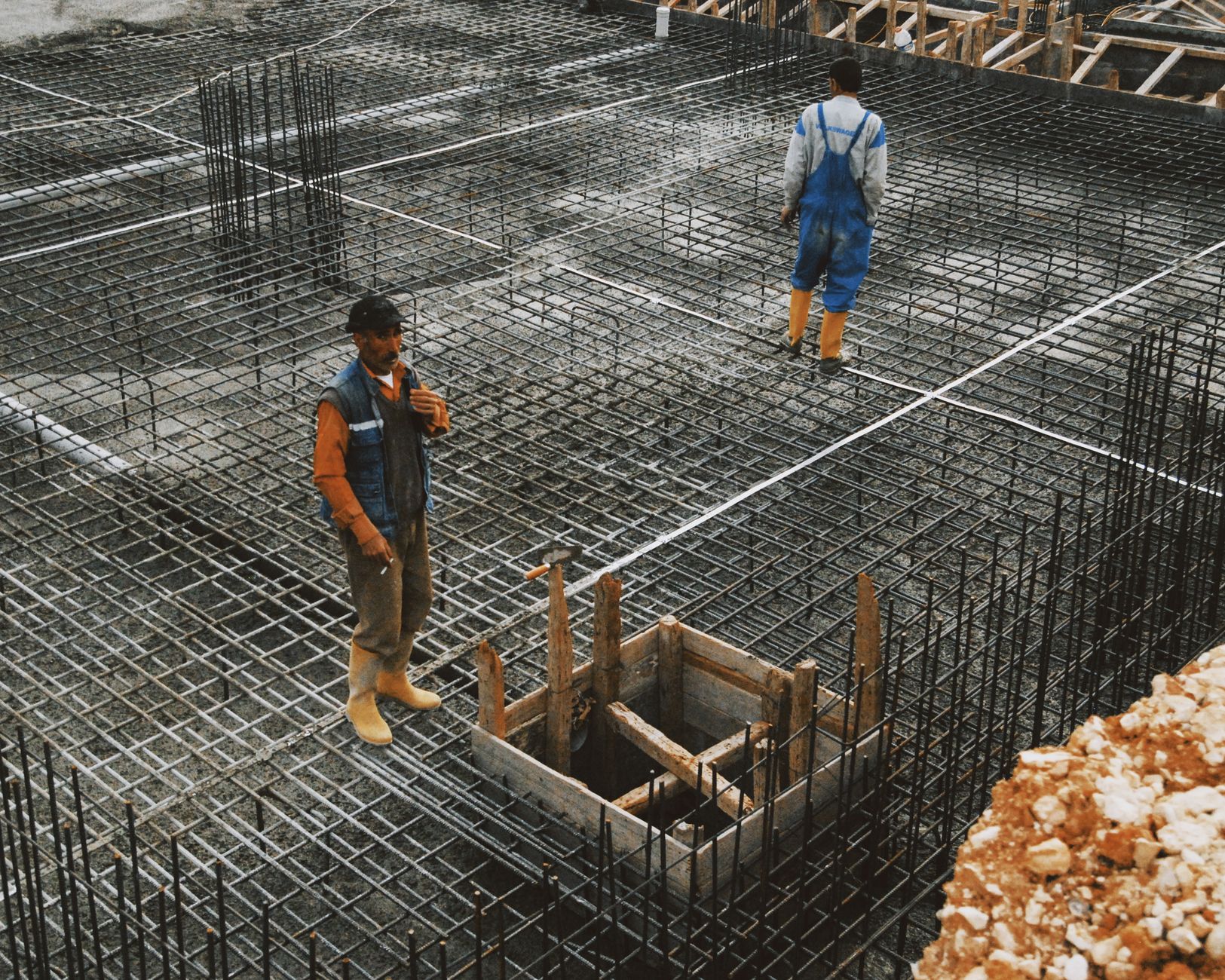
A raft foundation is, in essence, a single continuous slab spanning the entire footprint of a structure, carrying all of the loads on one combined base rather than a series of separate pads or strips. Rafts come into their own when the ground is weak or variable enough that individual footings would need to be so large that they would nearly touch one another anyway, at which point it becomes simpler and often cheaper to combine them into one slab. Spreading the total building load over the full footprint area keeps the bearing pressure low, and the stiffness of the slab itself helps bridge over localised soft spots that might otherwise cause a punishing amount of differential settlement under isolated footings.
Raft foundations come in several forms of increasing complexity and stiffness. A flat slab raft is simplest, a uniform thickness of reinforced concrete across the whole footprint. A beam-and-slab raft adds stiffening beams beneath the slab, typically aligned with the column grid, to increase stiffness where it is most needed without the cost of thickening the entire slab. Cellular rafts, built from a grid of walls and slabs forming a stiff box structure, are reserved for the heaviest loadings, such as tall buildings, where they are often combined with a basement and, on the most heavily loaded or tallest structures, with piles beneath the raft in what is known as a piled raft.
Rafts are particularly common on sites with variable made ground or fill, or in areas affected by historical mining subsidence, where the ability to bridge over localised weak zones is more valuable than the ability to resist very high bearing pressures. It is worth remembering that a raft controls differential settlement far more effectively than it controls total settlement: a raft over generally soft ground can still settle by a considerable amount overall, even while remaining almost perfectly level, and the serviceability of connecting services and access will need to accommodate that movement.
Piles
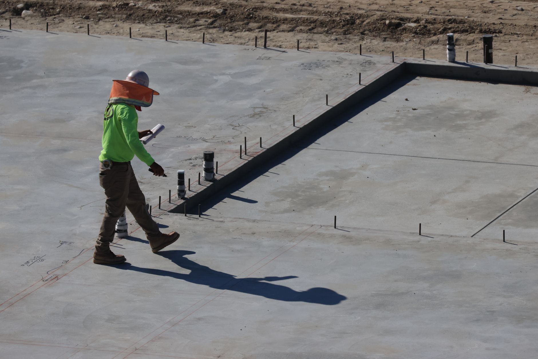
Piling is the answer when shallow foundations, however large, simply will not work: when the loads are too high, when suitable bearing strata lie too deep below the surface for a strip, pad, or raft to reach economically, or when the settlement of a shallow foundation would be unacceptably large. A pile transfers load down through weak or unsuitable ground to a point where it can be carried more effectively, either by end bearing, where the pile tip rests on or within a strong stratum capable of carrying the load directly, or by skin friction, also called shaft resistance, where load is transferred gradually along the length of the pile through adhesion and friction with the surrounding soil. Most piles rely on a combination of both mechanisms in varying proportions, depending on the ground profile.
Piles come in several distinct types. Driven piles, whether precast concrete or steel, are hammered or vibrated into the ground, displacing soil as they go and often densifying granular soils in the process, though the noise and vibration they generate can be a serious constraint on sites near existing structures or in urban areas. Bored, cast-in-situ piles are formed by drilling a hole, installing reinforcement, and filling it with concrete, offering a quieter installation and the ability to found at greater depth or in ground unsuitable for driving. Continuous flight auger piles combine elements of both, drilling and concreting in a single continuous operation as the auger is withdrawn, and screw piles use a helical shaft to achieve rapid installation with minimal spoil, particularly suited to lighter structures.
Piles are rarely used singly for anything other than light structures; more commonly, groups of piles are connected by a pile cap that distributes the load from a column or wall across the group. Pile groups behave differently from single isolated piles, because the zones of stressed ground around neighbouring piles overlap, reducing the efficiency of the group compared to the sum of its individual piles and increasing the settlement that must be checked for the group as a whole, not just for one pile in isolation.
Because a pile’s performance cannot be inspected directly once it is installed, testing plays an outsized role in pile foundation quality assurance. Static load tests, in which a test pile is loaded to or beyond its working load and its movement measured, provide the most direct evidence of capacity but are slow and expensive. Dynamic testing, using instrumentation to monitor stress waves during installation or under an impact load, offers a faster and cheaper way to estimate capacity across a larger proportion of a pile group. Integrity testing methods such as sonic echo testing or cross-hole sonic logging check bored piles for defects such as necking, voids, or poor concrete quality along the shaft, defects that would otherwise remain completely hidden beneath the ground.
Ground Improvement
Sometimes the most economical answer is not to choose between a shallow or a deep foundation, but to change the ground itself so that a shallow foundation becomes viable where it otherwise would not be. Ground improvement covers a wide range of techniques for increasing the strength, stiffness, or density of the ground, or for accelerating the rate at which it consolidates, and it can transform an unfavourable site into one where straightforward strip, pad, or raft foundations are perfectly adequate, often at a fraction of the cost of piling.
For loose granular soils, techniques such as vibro compaction use a vibrating probe to rearrange and densify the particles in place, while vibro stone columns go further, installing columns of compacted stone into cohesive or mixed ground to provide both reinforcement and enhanced drainage. Dynamic compaction, in which a heavy weight is repeatedly dropped from height across a grid pattern, densifies loose fill or granular deposits through the sheer energy of impact, and is particularly effective on sites with variable made ground where a more uniform, predictable response is needed before construction.
Soft clays present a different challenge, since they gain strength slowly as they consolidate under load, squeezing out pore water over months or years. Preloading, sometimes with a temporary surcharge of fill placed and later removed, accelerates this process, and vertical drains, thin wick drains installed on a grid across the site, shorten the drainage path and dramatically speed up consolidation that might otherwise take decades to occur naturally. Soil mixing, including lime and cement stabilisation, chemically alters the ground in place, binding particles together and increasing strength directly rather than relying on time and load to achieve the same result. Grouting techniques, from permeation grouting that fills voids in granular soils to jet grouting that erodes and mixes soil with cement in place, offer further options for strengthening ground or reducing its permeability, particularly in confined or sensitive locations where other methods are impractical.
Choosing between ground improvement and a deep foundation is rarely a purely technical decision; it also depends heavily on programme, cost, and practical constraints such as noise, vibration, and access, particularly on sites close to existing structures or sensitive neighbours. A technique that is ideal on an open greenfield site may be entirely unsuitable a few metres from an occupied building, and the final choice often comes down to whichever method delivers adequate, verifiable performance within the constraints the site actually presents.
None of these foundation types is inherently better than another; each is a tool suited to a particular combination of load, ground conditions, and site constraints, and a large part of a geotechnical engineer’s job is matching the right tool to the problem at hand rather than defaulting to whatever was used on the last project. Strip and pad foundations remain the workhorses of everyday construction on reasonable ground; rafts step in when the ground is too variable or too weak for isolated footings; piles reach past unsuitable ground entirely; and ground improvement changes the rules of the game so that a simpler foundation can be used after all. Understanding why each option exists, and what makes it the right or wrong choice for a given site, is the foundation, quite literally, of sound geotechnical design.


Leave a Reply